
Providing surge protection for military equipment
Electrical overstress, where excessive voltage or current is applied to an integrated circuit, is one of the main causes of IC failure and can also lead to a so-called ‘walking wounded’ product that continues to operate but constitutes a reliability hazard and may cause premature system failure. Steve Munns, Mil-Aero Marketing Manager, Linear Technology Corporation, explains how the military sector can protect against this.
Such risks have long been recognised and organisations and standards bodies responsible for equipment safety, reliability and performance have created specifications that are intended to protect electronic circuitry from a variety of potential overstress conditions. One such area is related to upstream power supply disturbances. This article focuses on the US Department of Defense Interface Standard MIL-STD-1275 which relates to 28V DC military vehicle power supplies and defines conditions that the equipment must survive.
Protecting against voltage surges, spikes and ripple
MIL-STD-1275 specifies three types of disturbance - voltage spikes of 250V for 70µs and 100V for 1ms originating from lightening strikes or inductive coupling of load steps. Solutions typically include using a transient voltage suppressor assisted by the required EMI filter circuits and the supply cable inductance.
Another disturbance is voltage surges of 100V for 50ms and 33V for 500ms resulting from load dumps where disconnection of a load circuit or battery induces a short and rapid increase in voltage across the alternator and therefore, in other loads sharing the same supply. This can be addressed by use of dedicated ICs featured in this article. Voltage ripple superimposed on the steady state rail of the incoming supply can present further challenges. Modest amplitude ripple can be filtered by the input capacitors to the protection circuit, but larger ripple and higher currents make it more practical and efficient to pass the ripple through the protection circuit to a downstream regulation stage.
Overvoltage protection circuits
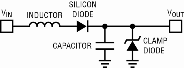
Traditional overvoltage protection with passives (Figure 1 - above) requires comparatively large and heavy components that introduce insertion losses which can become a problem as power demand increases. Shunting high energy levels to ground does not guarantee power delivery downstream and may result in damage to the passive components from repeated operations.
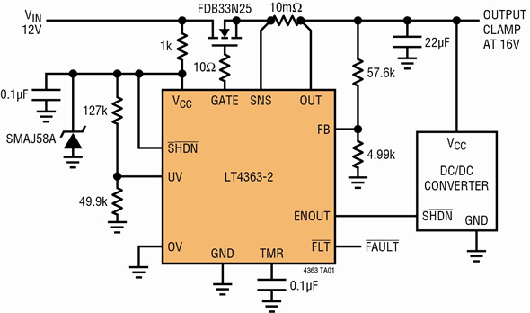
A better solution is a linear surge stopper IC that provides improved performance, overcurrent protection and additional functionality whilst reducing the board area needed. One example is the LT4363 High Voltage Surge Stopper (Figure 2 - below). This is referred to as a linear surge stopper since its operation is analogous to a linear voltage regulator.
Under normal operation, an external N-channel MOSFET is driven fully on and acts as a pass device with very little voltage drop. If the output voltage rises above the regulation point set by a resistive divider at the FB pin, the MOSFET regulates the voltage at the OUT pin allowing the load circuit to continue to operate through the transient event.
Switching surge stopper
Linear surge stoppers provide a solution for systems requiring up to approximately 4A of current, beyond which the ability of the circuit to ride-through long surges effectively becomes limited. For larger currents a more efficient solution is now available through the use of dedicated switching regulator technology where the limitation primarily becomes one of system thermal mass and associated maximum junction temperature considerations.
The LTC7860 is designed for use as a high efficiency switching surge stopper and/or input inrush current limiter. In normal operation the LTC7860 is in dropout or SWITCH-ON mode with the external MOSFET driven continuously.
The LTC7860 switches during start-up or in response to either an input overvoltage or output short circuit event by entering the PROTECTIVE PWM mode. The output voltage is regulated to a safe level allowing the load to operate through the input overvoltage event. An internal comparator limits the voltage across the current sense resistor and regulates the maximum output current to protect against overcurrent faults.
An adjustable timer limits the time that the LTC7860 can spend in overvoltage or overcurrent regulation, turning off the external MOSFET until the LTC7860 restarts after a cool down period.
The 60V maximum VIN to SGND range can be extended to more than 200V by use of a shunt regulator to supply bias to the LTC7860. The operational input voltage of the circuit is then limited by the rating of the external components.
Conclusion
Dedicated surge stopper ICs provide superior performance to passive circuit protection and help to meet the size, weight and power reductions that are being demanded of future systems.
Product Spotlight
APV1111GVY
Panasonic

Panasonic PhotoMOS® Photovoltaic MOSFET High-Power Drivers
| SKU: | |
|---|---|
| Stock: | 3490 |
| Cost: | $3.95 |
